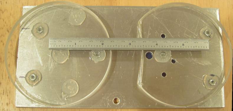
Test secondary mirror silicone bonding technique by bonding two old windows to an aluminum plate. One window uses three bond pads, the other used five bond pads. Each bond pad area is between 15 mm and 20 mm diameter after pressing flat.
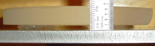
The space between the aluminum plate and the glass was about 2 mm. After curing for two days, I tested the bond strength by pulling them apart by hand. I had to pull with considerable force, estimated at 30 pounds, before I could separate the 3-bond pair. The 5-bond pair took about the same amount, probably because the force tended to elongate one pad a time. While this test was at room temperature, it showed that three bond pads seem a very safe bet to hold onto the 3.1" secondary mirror. The silicone pads remained stuck to the glass - they all came off the aluminum plate. As long as the plastic secondary holder adheres well to the silicone, the mirror should be safe.
![]()
The 3.1" diameter Protostar heated secondary holder used three nylon spacers, each about 1/8" thick. I bonded these to the holder with small dabs of epoxy.
The secondary was held in a small vise with the mirror held level so that it would not move during the cure. The #34 gauge wires coming out from between the secondary and the holder lead to a temperature sensor bonded to the back of the mirror.
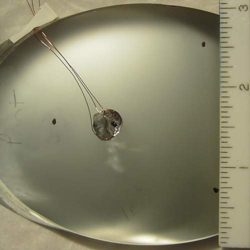
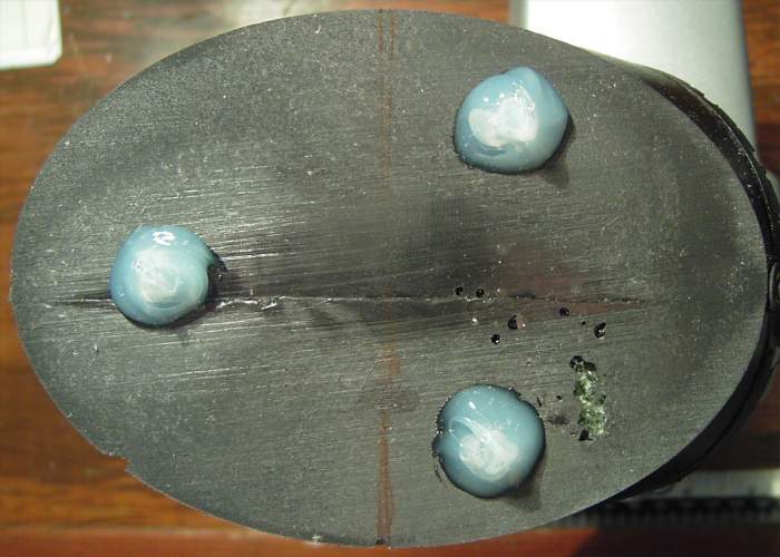
A small LM20 sensor (SC70-5 package, roughly 2 mm square, 1 mm thick) was bonded to the back of the secondary mirror to measure its temperature. The three dots are where the bond pads will fall. The air temperature and the tube inside temperature will also be monitored with calibrated sensors of the same type. This should allow good control of temperature differentials for all the optics down to about 0.05 C.
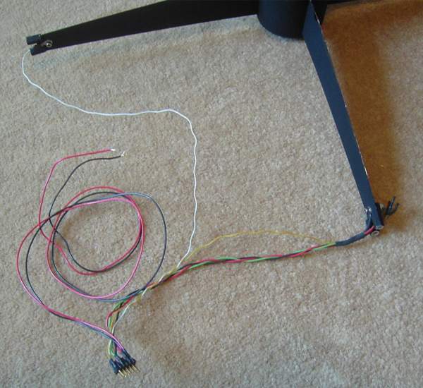
I needed the three wires for the temperature sensor to come down the vanes, and since I had to add these, I decided to modify the heater connections, as well. The five wires, along with two more wires for an illuminated reticle in a finder scope, all connect to gold pins that I can disconnect together.
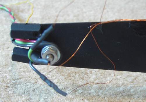
I drilled a small hole in the secondary vane and used a wire lug to bring out the heater contacts to a more solid connection. The same bolt provided strain relief for the fine temperature sensor wires.
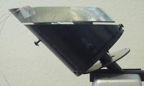
I ran the #36 gauge enameled wires down the side of the secondary mirror holder and then along the bottom of a vane. Epoxy holds the wires in place until the outer edge, where the optics can't see them.

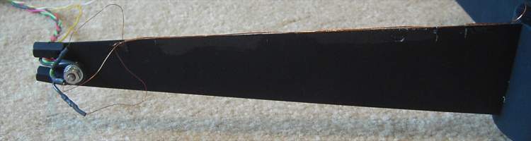
Looking down the vane shows that the wires do not add appreciable width to the obscuration, minimizing diffraction effects.
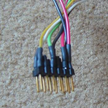
The 12-pin connector uses grounds on one side, signals on the other.
Links to other Stellar Products pages: