[Reprinted in "Milestones in Optics", SPIE
Donald G. Bruns
5441 West 122nd Street, Hawthorne, California, 90250.
The optical testing of the secondary mirror is of prime concern in construction of a Cassegrain telescope. The superior performance designs are usually those which are the most difficult to test (1). The Ritchey-Chretien design is currently being used or being considered for most new large telescopes, because use of hyperbolic surfaces on both the concave primary mirror and the convex secondary mirror yields a coma-free image. The optical testing of a hyperbolic convex mirror, however, is not a trivial task. Most conventional tests are subject to cumulative errors caused by several auxiliary reflections, and most require repeated zonal testing. The purpose of this Letter is to suggest a new null test related to the Gaviola test (2). This variation requires construction of a null lens which eliminates the second set of measurements, giving an immediate null with the first testing. Calculations are presented which show the required surface figure of this auxiliary null lens to be hyperbolic instead of spherical. The perfect focusing properties of this null lens makes it easy to figure. The only restrictions to this test relate the mirror amplification factor m (the ratio of primary mirror and system focal lengths) to the refractive index of the null lens. In this case, however, the restriction is not severe, because the null lens is only used in the optical testing phase, and commonly available glasses allow a range of m from 1.71 to 3.51, sufficient to cover most telescope designs. Ray tracing results are shown for a typical case along with the residual wave front error. The effects of small lens variations are also presented.
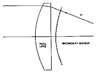
This proposed null test takes advantage of the spherical aberration of a plano-convex lens. The convex surface must be hyperbolic in cross section with an eccentricity e equal to the refractive index n of the glass. Plane wave monochromatic light incident on the flat surface will then emerge perfectly spherical, focusing at a distance f = R/(e - 1) from the vertex of the convex surface, where R is the vertex radius of curvature. This property makes the lens as easy to figure as the reference sphere. When the lens is used in reverse, however, as shown in Fig. 1, it has just the right amount of spherical aberration to cancel that of a hyperbolic convex mirror whose eccentricity e' is not equal to n. Third-order aberration theory is sufficient to show this and provides the relationship between e' and n.
Fig. 1. Orientation of optical elements during the null test. The plano-convex null lens has refractive index n and a hyperbolic surface with eccentricity e. The convex secondary mirror has a vertex radius R' and a hyperbolic surface with eccentricity e'. Collimated monochromatic light is incident from the left.
The longitudinal spherical aberration (LSA) of a thin plano-convex lens used with an infinitely distant object is given by Born and Wolf (3) as
LSA = r^2(e^2 - n^2)/(2f*(n - 1)^2),
where r is the ray intersection height on the lens, and f is the paraxial focal length of the lens. The spherical aberration is seen to be zero if e = n. The same lens, used in a convex-plano configuration, has longitudinal spherical aberration given by
LSA = r^2((e^2)*n - n^3 + 2n^2 - 2)/(2fn(n - 1)^2).
When e = n,
LSA = r^2(n+ 1)/(fn(n-1)).
The longitudinal spherical aberration of a convex mirror measured near its center of curvature is easily shown to be
LSA’ = (r’^2)*(e’^2)/(2R’),
where the primes refer to the mirror. If the lens is separated by a distance d from the mirror and f = R’ + d, then r/r’ = f/R’, and the spherical aberration of the optical pair will vanish if
e’^2 = 2(n+1)(R'+d)/(n(n - 1)R').
If n varies from 1.46 to 1.80, e’^2 varies from 7.33 to 3.89 when d = 0, and if the diameter of the lens is allowed to be double that of the mirror, e’^2 can be increased to 14.65.
These values of e’^2 are appropriate for Cassegrain telescopes. The classical Cassegrain requires a value of m = (e’ + 1)/(e'- 1), where m is the secondary magnification. Substituting the values of e’^2 found above, the available magnifications vary from 1.71 to 3.06. The Ritchey-Chretien telescope design requires a slightly lower value of e’^2 for the same magnification. If the image distance behind the primary mirror is b, the primary mirror focal ratio is F, and the primary mirror diameter is D (4),
e’^2 = 1 + (2mF(m+1)/(((m-1)^3)(mF - b/D)) + 4m/(m-1)^2) .
Consider a typical design with a secondary image distance b = D and F from 2 to 4. Then lens refractive indices from 1.46 to 1.80 allow m to vary from 2.04 to 3.51, using the same values of e’^2 used earlier. These are again typical values for Ritchey-Chretien telescopes and show the general usefulness of this null test.
Geometrical ray tracing results show that the peak-to-peak wave front error in this null test is usually much smaller than one-fortieth of a wavelength of red light for properly chosen combinations. The smallest residual errors result from using higher-index glasses and thin lenses. As an example, an 80-mm diam secondary mirror of 457.2-mm vertex radius and eccentricity 2.303 requires a 7.62-mm thick null lens with a back focal length of 457.2 mm and refractive index 1.61674 (Schott F-2 glass at 633 nm) to be placed in contact to achieve the best null according to ray trace calculations. The peak-to-peak wave front error is then <0.013 wavelengths of red light. Applying the third-order thin lens formula found above results in a best null for a zero thickness lens of 462-mm focal length and refractive index 1.61674 when placed 4.8 mm from the mirror. This is very good agreement with the ray tracing results.
The mirror can he figured only to the accuracy of the null lens. Not only must the lens surfaces be free of zonal errors and irregularities, but also the plano-surface must not contribute its own spherical aberration due to its error in flatness. Using simple aberration theory again, the amount of allowed curvature or lens sag can be calculated. Specifically, the sag s in the lens surface which produces an incorrect longitudinal spherical aberration of amount z is
s = ((nzr^4)/((4f^2)*(n^4 -3n^3 +2n^2 +2n - 2)))^(1/3).
For the 80-mm diam, 457.2-mm focal length lens in the above example, the sag at the center or edges must be less than ~0.08 mm for an error of one-tenth of a red wavelength of light. Flatness of this accuracy is easy to achieve.
While hyperbolic surfaced lenses are not usually mass produced to the quality and accuracy required here, their ease of testing should make them no more difficult to figure than simple parabolic mirrors. Use of a laser interferometer should make testing both the lenses and mirrors relatively simple, allowing the primary work effort to concentrate on producing good figures. The production of the large asphericities required of the null lens and the necessity for a large diameter well-collimated monochromatic light source will provide a challenge to the amateur telescope maker, but this new test could become a powerful tool for a mass producer. For a completed null lens, the permitted values of e’ and R’ range over a very restricted region, depending on the surface accuracy desired and the nominal mirror specifications. This null test should make the design of future telescopes somewhat easier and can be used to test the figures of secondary mirrors already made.
References